3D Printing - Test Tile Extruder Die
General Info about my extruder and the process -
I am making this Test Tile Die to fit my die adapter for my Bailey 9 extruder. If you want to read more info about the die adapter and spacers I made - see my other post here
If you have a Bailey 4 or Bailey 5 extruder - you can ignore my rambling about the die adapters and spacers. These dies I made for my extruder at their current measurements will work just fine in your Bailey 4 or Bailey 5 extruder!
Other extruder brands and models - I haven’t tested these dies in any other extruders yet. As long as your extruder has some wiggle room on die size and thickness, these dies at the sizes they are should work. But for brands where the die has to be very specific dimensions you’ll have to do some measuring.
To Design Your Die You’ll Need -
CAD Software or Program
Tinkercad
I don’t have much CAD experience, but I’m familiar with Adobe programs and generally computer savvy so I started with Tinkercad. It’s a free online based program. It’s great for beginners and easy projects, but lacks a lot of advanced features and functionality. My preference now would be to learn how to use Fusion360, but that’s gonna be a bigger learning curve for sure.
Optional - Fusion 360
This software is an expanded version of tinkercad and fully functional CAD software. I haven’t had time to learn it, but I have exported my tinkercad objects to it to add bevels, chamfers, and filets. Pretty easy even when you don’t have experience with the program. Here’s a YouTube video about that -
3D Printer
You need one that can print PLA or PETG and has a big enough print bed to accommodate the size of the die you will be making. I had a Creality K1 when I originally was printing these dies. Now I have a Bambu P1S and Bambu A1.
Slicing Software for STL Print File
I was using Orca slicer with my Creality printer and I’m using Bambu’s slicer now, which is basically the same as Orca. I haven’t had any issues with it.
My print settings were .22 layer height and 100% infill. That much infill is probably overkill to be honest, but I didn’t mind using the extra filament and I wanted to be sure these dies would last and not warp.
PLA/PETG Filament
So far, I’ve been making the dies with PLA and it has worked out just fine. After some use I’ve noticed a small bit of warping on one die, but I think that particular die was made with less infill. PETG does have better water resistance, but it is not as pliable as PLA and I felt it might be more prone to snapping under the pressure of the downward force. I think either material will be just fine though and it might come down to personal preference.
Making A Test Tile Die in TinkerCad
Okay, I’m gonna walk you through every step I took to make this die on TinkerCad. If you’ve never used TinkerCad before this might be a little intense to start with. You can go through some of the tutorials and lessons on TinkerCad first and then give this a go.
Let’s go for it -
My die holder board has an open area of 5x6 inches. The inner routed edge is about .4 inches deep.
We’re going to be working in inches because that’s what my die holder and extruder were measured in and I didn’t want to mess with millimeters. But that’s up to you.
First thing I did in TinkerCad was change the setting from Metric to Imperial measurement.
Main Die Shape
Shape 1
Pull a red box into the workspace on tinkercad
Make it 5.9in x 4.9in and .4in tall
Radius to .014 (mostly for aesthetics, but also avoids sharp edge which makes it easier to fit into holder)
Steps to maximum (gives more detail)
Shape 2
Pull another red box in
Change color to blue
Size to 4x4, height to .5in
(This box is just for visuals so I know how much space I’m working with. The actual extrusion area is going to be 4x4 inches to match the width of the upper barrel of my extruder. Anything beyond that 4x4 barrier is not going to be extruded. )
Move both Shape 1 and 2 off to the side of your workplane - out of your way for now
Test Tile Shape
This is where your preference for the style and shape of test tile comes in. I like a tall tile with a wide base to make sure it doesn’t tip over and 3-5 half circle bump outs to show how the glaze might break on texture.
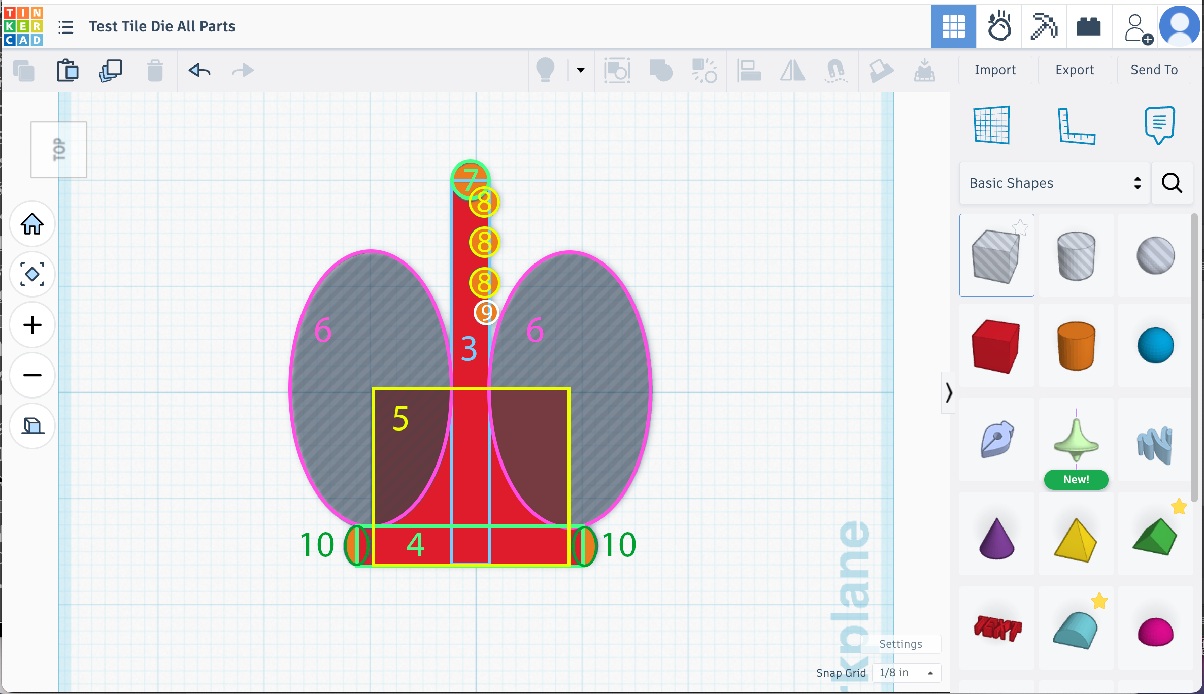
Shape 3 - This is just the general long length of your test tile.
Pull in a red box
steps to maximum
dimensions 3.6in long x .35in wide x 1in height
Shape 4 - This will be the start of our base/bottom.
Pull in a red box
steps to maximum
set size to 2.125in x .35 in x 1in
Shape 5 - This gives us some weight and thickness at the base.
Grab another box
steps to maximum
dimensions 1.65in x 1.85in x 1in
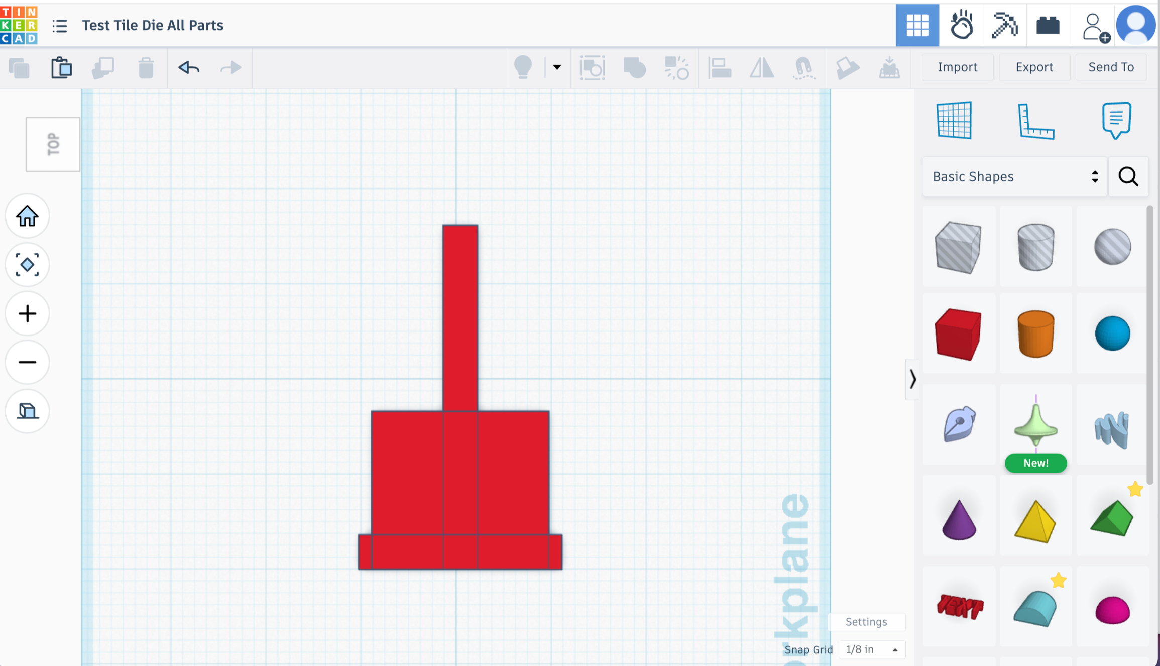
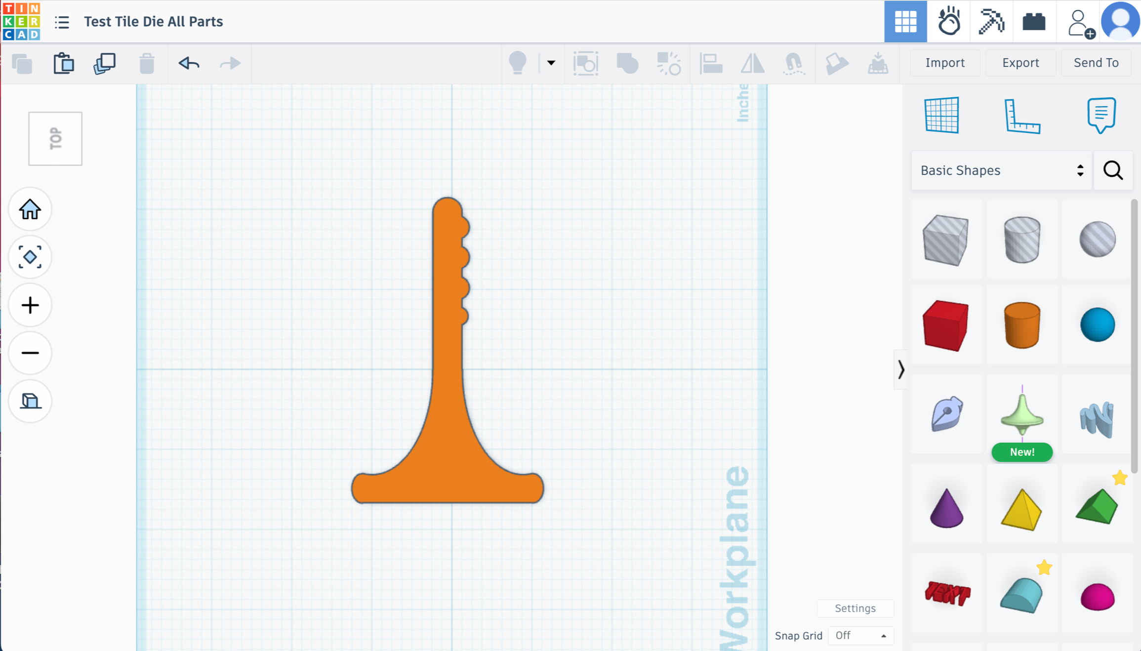
Align parts 1-3 to center horizontally. Then align them all to the bottom.
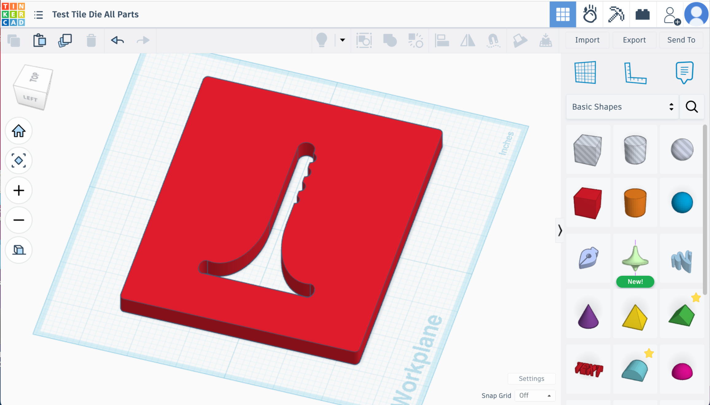
It should look like this -
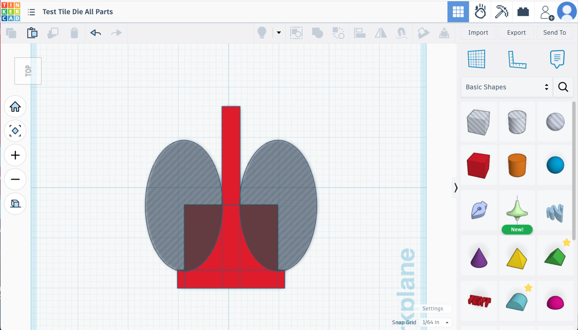
Shape 6
Pull in a hole cylinder
segments to maximum
sides to maximum
dimensions 2.6in x 1.53in x 1.25 in
Duplicate.
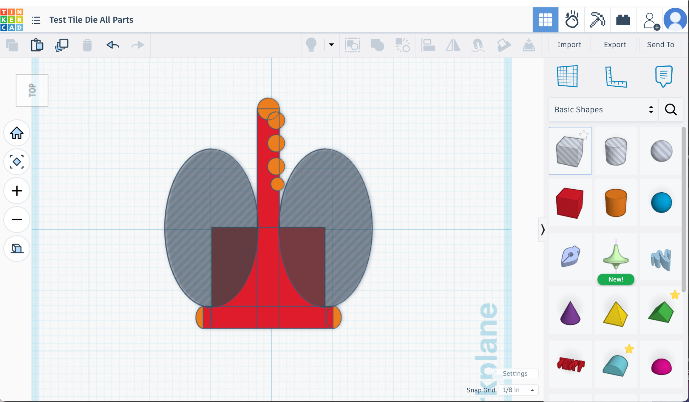
Align to the bottom and edge of the test tile on both sides as shown in the pic below.
I like to push it slightly down into the bottom section to create a small divet down there which can help to catch super runny glazes. You may have to zoom in really good to get those ovals aligned well with the side and just slightly pushing down into the bottom.
Union Group all parts
Tip - Changing the “Snap Grid” setting will allow you to move your shapes just a tiny bit at a time. That setting in on the lower right side of your workplane screen. You’ll want that to be set to “off” or “1/64th” to get the most control over moving your shapes.
Shape 7 - Rounds out the top.
Grab a cylinder
sides and segments to maximum
dimensions .35in x .35in x 1in
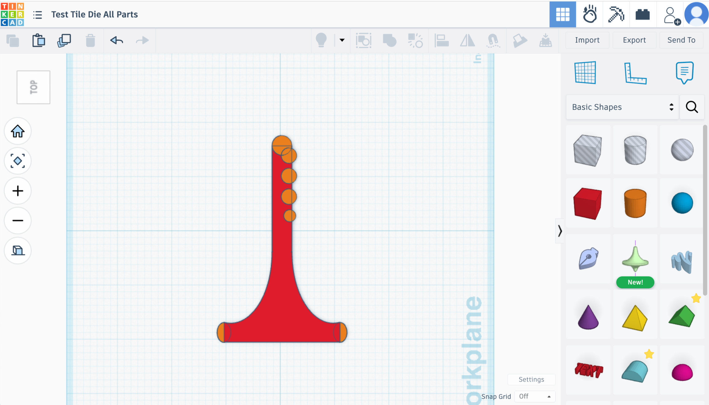
Put that at the top of the test tile, sticking out halfway, to make the top round.
Shape 8 - These are the texture bump outs.
Grab another cylinder
sides and segments to maximum
Dimensions .275in x .275in x 1in
Duplicate it twice so you have 3 total.
Intersect these about 2/3rds of the way onto the main test tile. 1/3rd of the way sticking out. Space them out however you’d like. I have mine about 1/8in apart.
Shape 9 - One more texture bump out.
Duplicate one of the Shape 8 circles.
make it .2in x .2in × 1in
Intersect it about 1/3 of the way sticking out below the others.
Select all of the objects on the workplace and Union Group
(You can change those texture bumps around however you want for your specific needs, but this is how I do mine.)
Shape 10 - Rounding out the bottom ends.
Pull in a cylinder
size to .24 in x .35 in x 1 in
sides and segments to max
Duplicate.
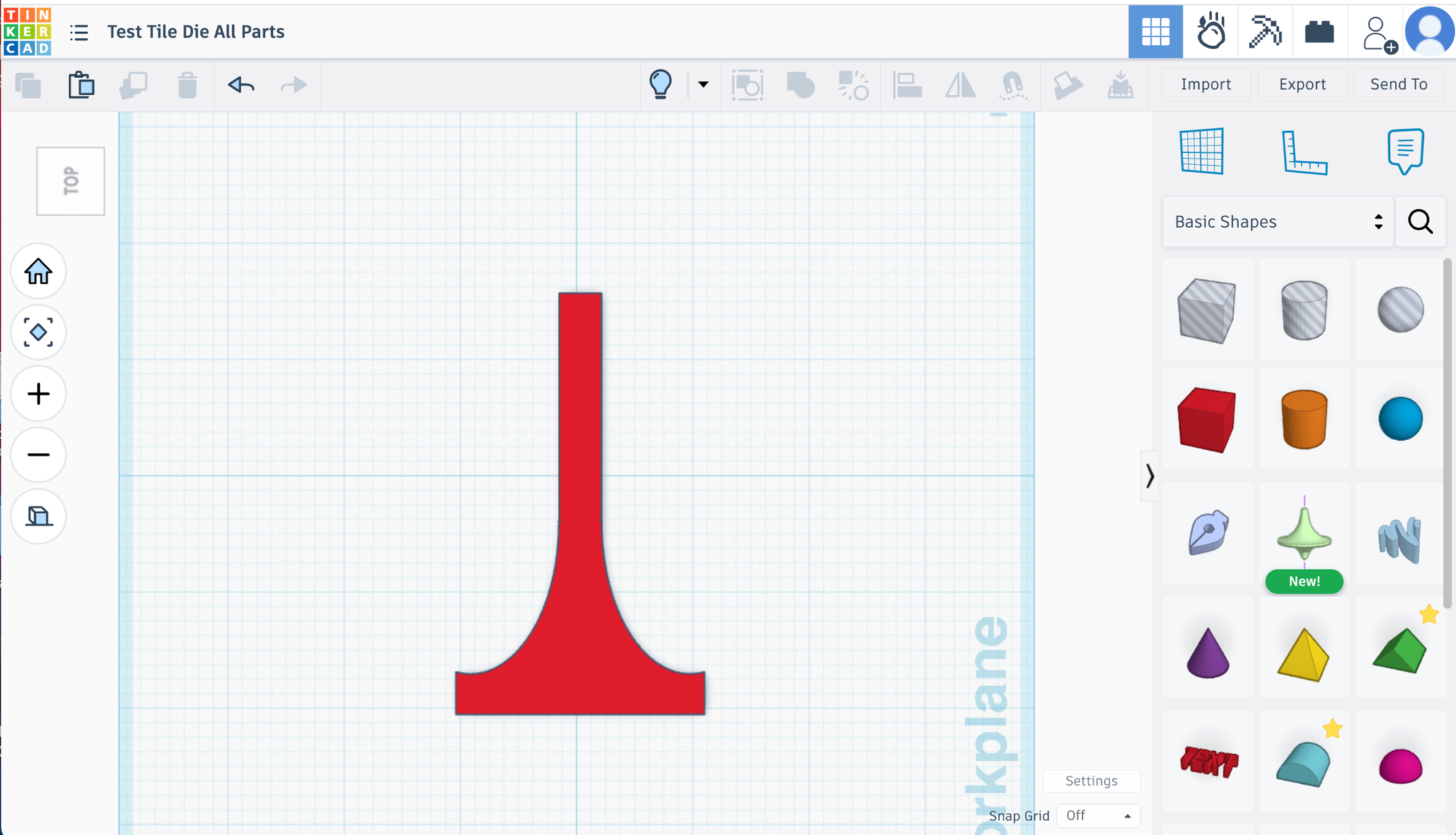
Align each cylinder halfway sticking out and halfway intersecting on both ends of the bottom (shape 4)
Union Group to create one object
Your test tile shape is done!
Final Steps
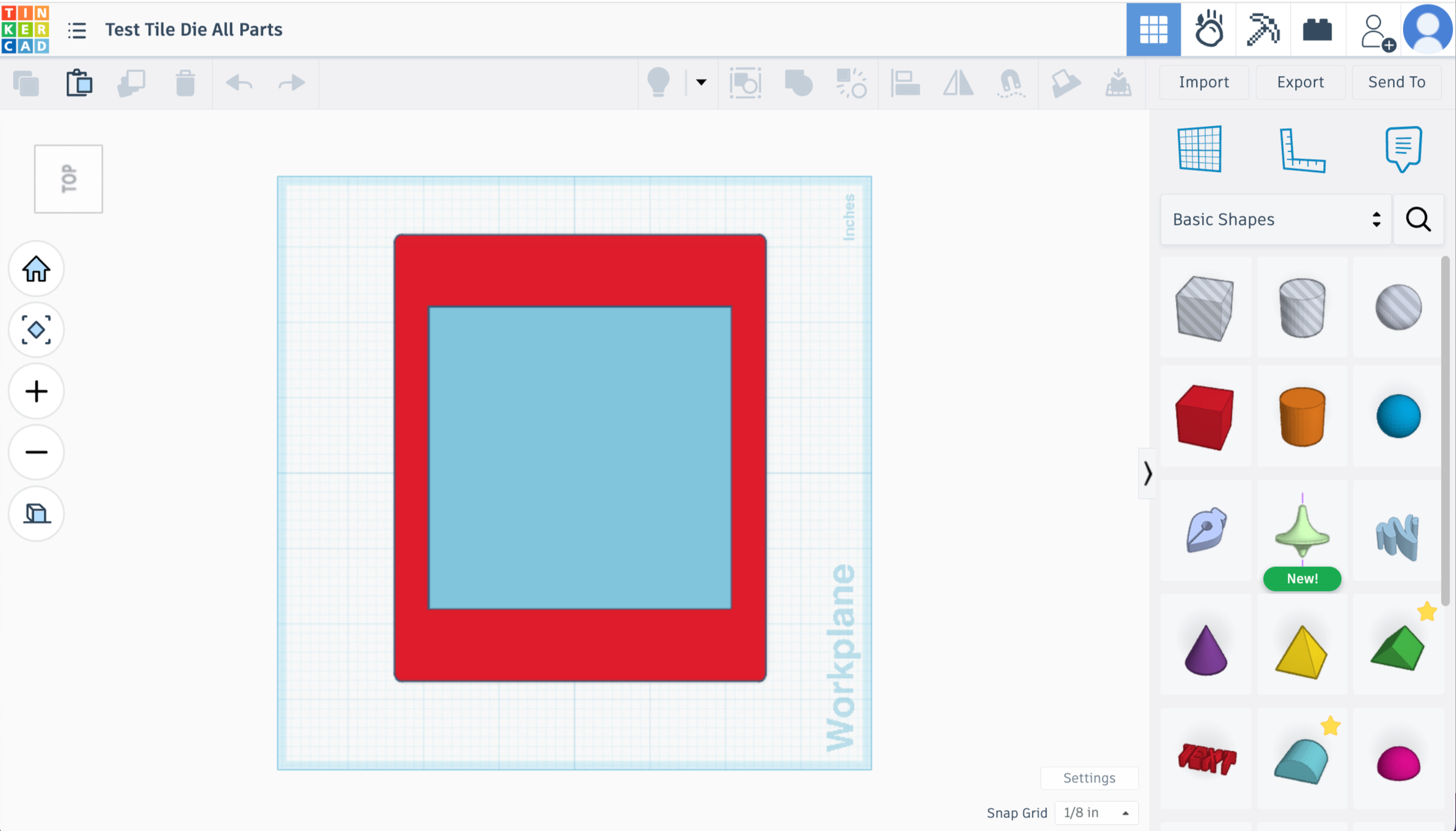
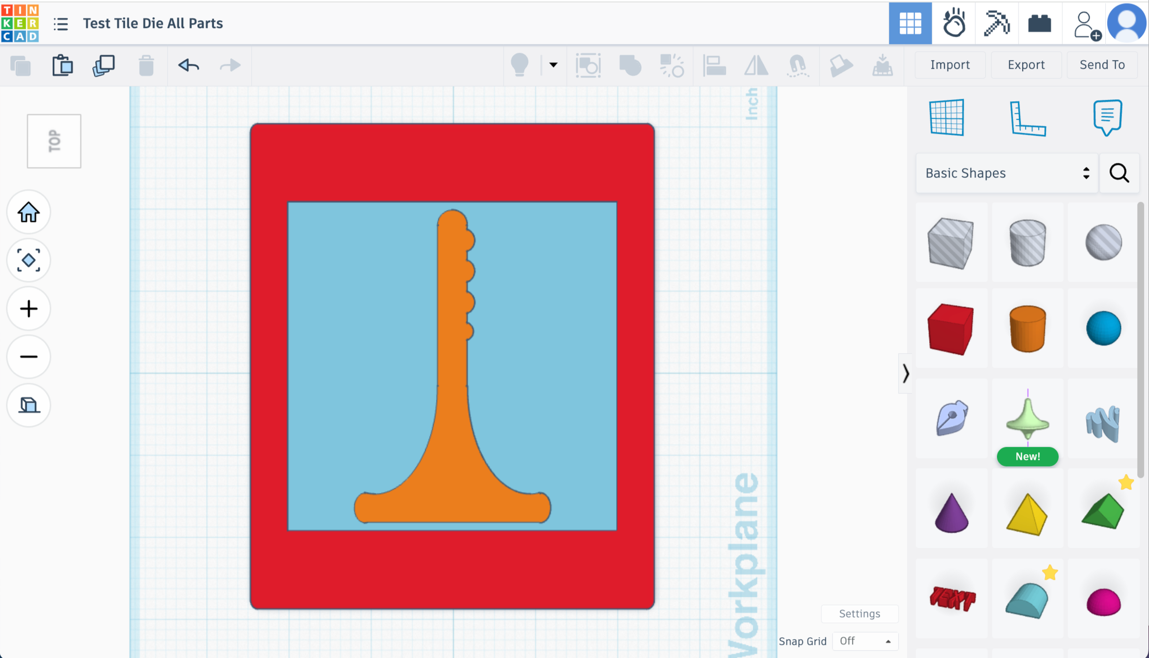
Select Shape 1, Shape 2 from back in the beginning and your test tile shape - Align centered horizontally and vertically
Make sure the test tile shape fits nicely within the 4x4 blue box border. If so, delete the blue box.
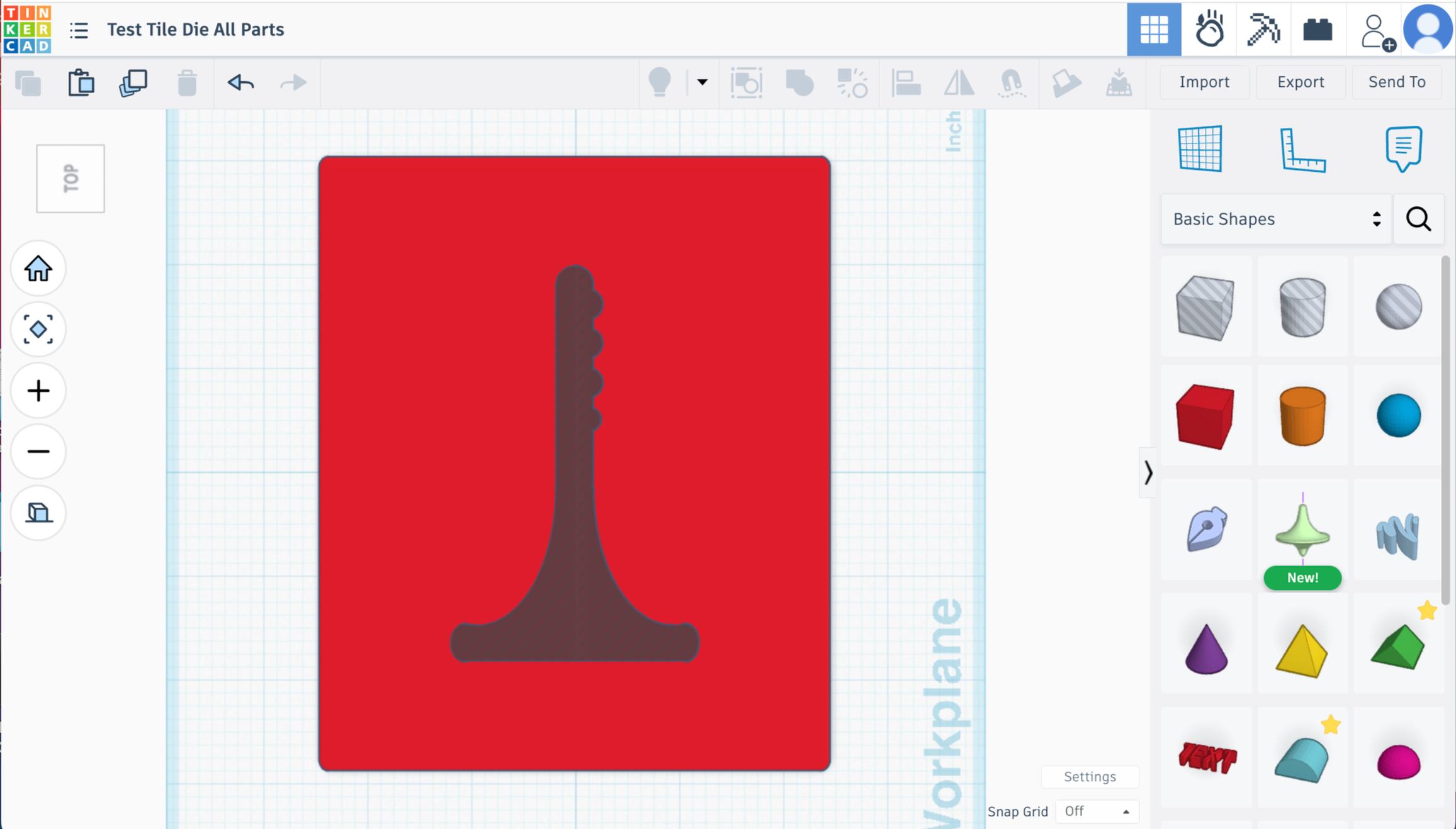
Turn the test tile shape from solid to hole
Union group the main die shape 1 and the test tile shape.
Now you have a test tile die!!
Let’s talk about bevels and chamfers -
Okay this is where I got super annoyed at how hard it is to add bevels, chamfers or filets in TinkerCad. It’s possible, but takes forever for complicated shapes the test tile. For regular shapes like circles, squares, triangles, etc - it’s way easier. You can export this file from TinkerCad directly into Fusion360 to add chamfers or bevels that way. It’s still a little weird since the shape is complicated. And it wouldn’t allow me to get a deep or wide enough bevel for what I wanted. But I’ll let you explore that if you’d like!
Do you need a bevel at the top to help guide the clay? Probably not, to be honest. I liked the look of it and felt like it was helping the clay come out cleaner. But, at the end of the day, a lot of commercial dies don’t have the bevel and people use them all the time with success. So that’s up to you!
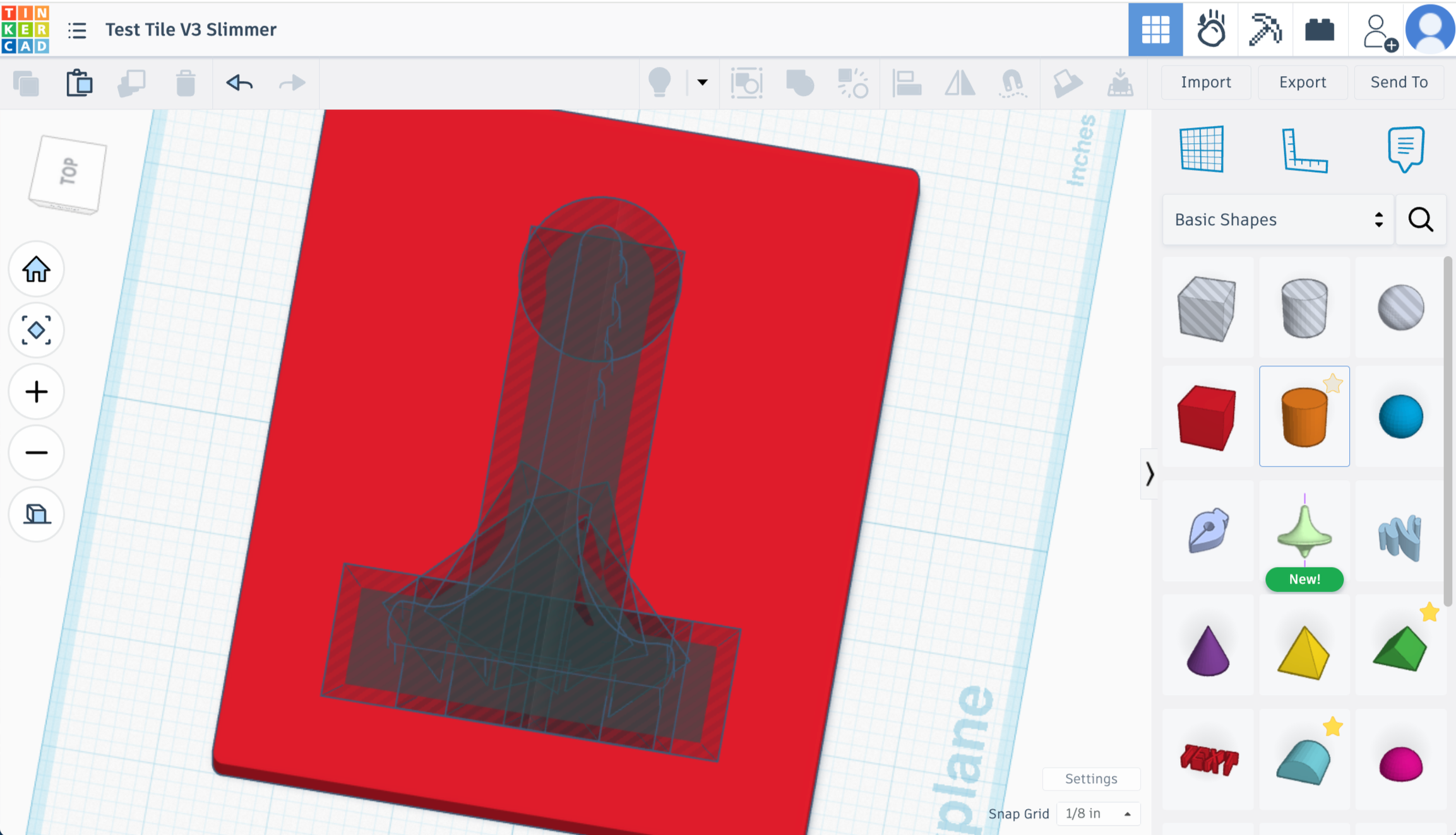
If you do want to try it out on TinkerCad for the test tile die - here’s a pic of how I used the Cone shape (sides to 4) and the Cone shape (sides to maximum) to get the effect. I messed around with it adding a lot of them in as holes. It was a pain in the butt and I don’t really recommend it unless you’re feeling committed to the bevel. You can do it a little quicker and dirtier if you don’t mind the bevel looking kinda crazy, but I was going for as smooth as possible and I still couldn’t quite get it. If anyone is familiar with TinkerCad and knows a better way I am all ears!

Let me know if this post helped you out! I love to hear from people! Send me a message on instagram or shoot me an email!