3D Printing - Hollow Extruder Dies
General Info about my extruder and the process -
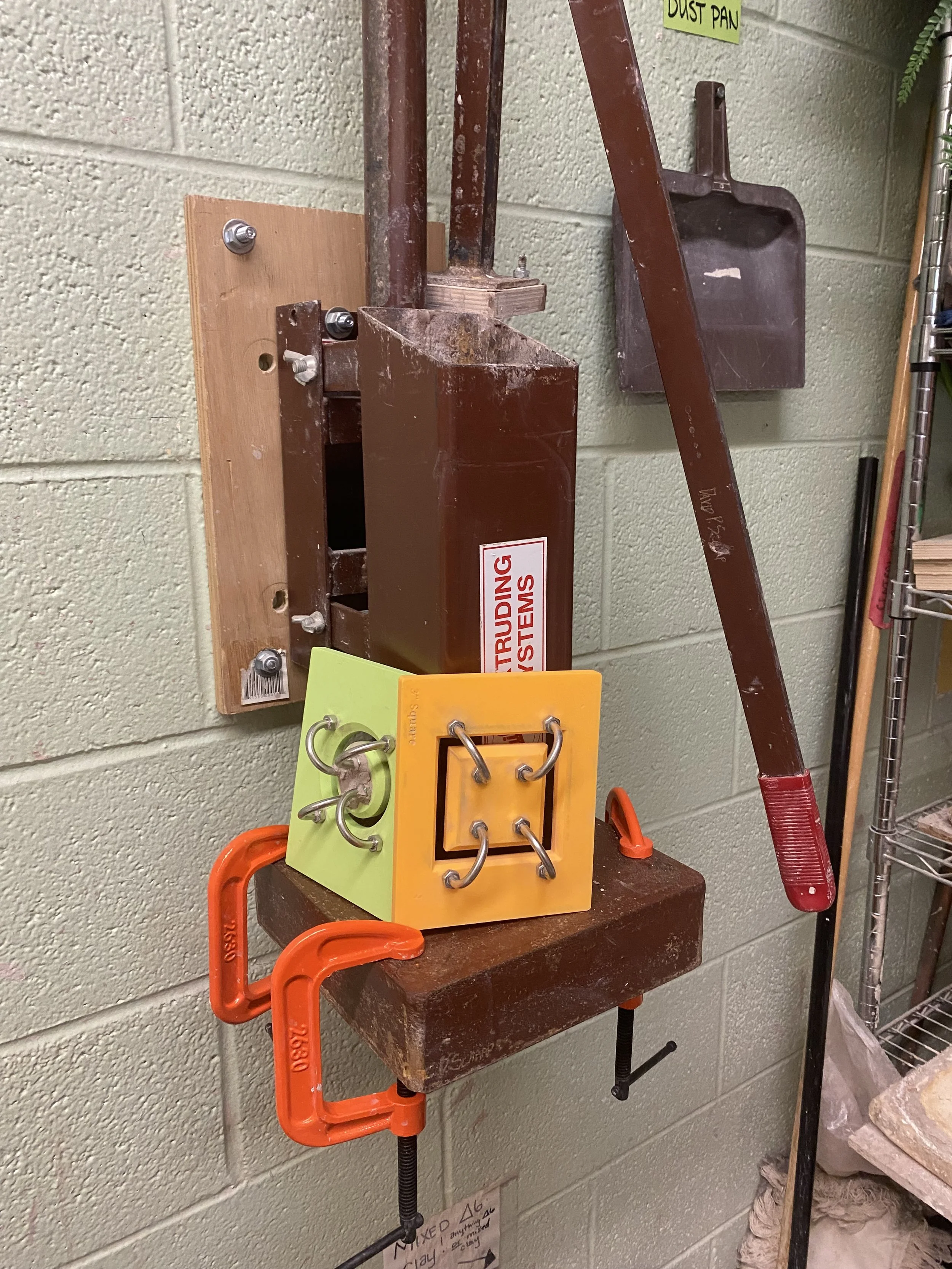
3D printed extruder dies made by me! I got this large Bailey extruder for a steal of a deal and because I’m a cheap ass - I didn’t want to buy dies.
My Bailey Standard 9 Extruder is an older model by far. So My upper barrel is 4 inches and lower is 9. The new models of the Standard 9 have a 5 inch upper barrel (lucky!) Make sure you measure your extruder for the actual dimensions. The inner dimensions of the barrels on mine are closer to 3.5 inches and 8.5 inches.
If you have a Bailey 9 Extruder - These dies are made to fit into the die adapter, but the inset part is only 1/4 inch deep on the Bailey adapter. A 3d printed die needs to be thicker than 1/4 in to be sturdy enough in my opinion. The 3D printed die will stick up above the the inset part, but I don’t think that will have an effect on the extrusion. If you try it - please let me know. I made my own die adapter and spacers with a deeper inset - you can read about those here.
If you have a Bailey 4 or Bailey 5 extruder - you can ignore my rambling about the die adapters and spacers. These dies I made for my extruder at their current measurements will work just fine in your Bailey 4 or Bailey 5 extruder!
Other extruder brands and models - I haven’t tested these dies in any other extruders yet. As long as your extruder has some wiggle room on die size and thickness, these dies should work. But for brands where the die has to be very specific dimensions you’ll have to do some measuring and changing.
To Design Your Die You’ll Need -
CAD Software or Program
Tinkercad
I don’t have much CAD experience, but I’m familiar with Adobe programs and generally computer savvy so I started with Tinkercad. It’s a free online based program. It’s great for beginners and easy projects, but lacks a lot of advanced features and functionality. My preference now would be to learn how to use Fusion360, but that’s gonna be a bigger learning curve for sure.
Optional - Fusion 360
This software is an expanded version of tinkercad and fully functional CAD software. I haven’t had time to learn it, but I have exported my tinkercad objects to it to add bevels, chamfers, and filets. Pretty easy even when you don’t have experience with the program. Here’s a YouTube video about that -
3D Printer
You need one that can print PLA or PETG and has a big enough print bed to accommodate the size of the die you will be making. I had a Creality K1 when I originally was printing these dies. Now I have a Bambu P1S and Bambu A1.
Slicing Software for STL Print File
I was using Orca slicer with my Creality printer and I’m using Bambu’s slicer now, which is basically the same as Orca. I haven’t had any issues with it.
My print settings were .22 layer height and 100% infill. That much infill is probably overkill to be honest, but I didn’t mind using the extra filament and I wanted to be sure these dies would last and not warp.
PLA/PETG Filament
So far, I’ve been making the dies with PLA and it has worked out just fine. After some use I’ve noticed a small bit of warping on one die, but I think that particular die was made with less infill. PETG does have better water resistance, but it is not as pliable as PLA and I felt it might be more prone to snapping under the pressure of the downward force. I think either material will be just fine though and it might come down to personal preference.
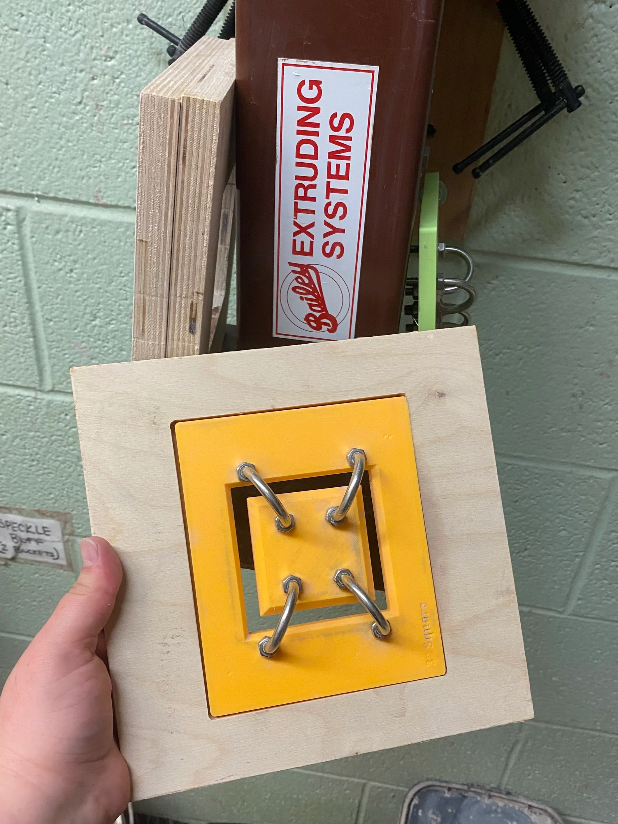
U-Bolts for Hollow Dies
This is where I had the most trouble. You will need to purchase your bolts BEFORE you start designing. Most manufacturers will have measurements of their bolts available, but I found that those measurements weren’t always accurate. Plus you end up with slight differences in the printed die than the design because of variations in the 3D Printer, shrinkage and stuff with the PLA/PETG. So you may need to adjust. Get some calipers! (Not the pottery ones.)
The placement of the holes for the U-Bolts is very important because you want that inner die part to be perfectly held in the center. If it’s slightly off there will be uneven walls in your extrusion. You don’t want to force them too hard into holes that are slightly off because it puts extra pressure on the die.
One of the things I find annoying about the Bailey dies is that the hollow ones don’t come with the center bar for every die. So unless you want to buy a center bar for every die, you have to take it off and on all the time. That’s just asking for parts to get lost in a community studio and it’s annoying. I make my dies with their own u-bolts that will ideally never have to be removed. I used 4 bolts in each hollow die design. Again, you need enough strength in the die itself to withstand the force of the plunger pushing the clay down against it. Just having 2 did not feel like it would be enough.
Don’t forget that the nuts on the U-Bolt will stick out farther than the bolt itself. The entire assembly needs to fit up inside the barrel of your extruder for the Bailey 4 and 5. For the Bailey 9 - if you use spacers - it does not need to fit up inside the barrel.
Also consider the height of the bolts. The extruder plunger has to stop when it comes into contact with the bolts. that limits the amount of clay you can load into the barrel each time.
Here are the ones I bought from Amazon - M6x25mm 304 Stainless Steel U-Bolt Fastener https://www.amazon.com/dp/B09KXPR1C9?ref_=ppx_hzsearch_conn_dt_b_fed_asin_title_3&th=1
Hollow Square Die (3 inches)
This is the yellow one in the pictures.
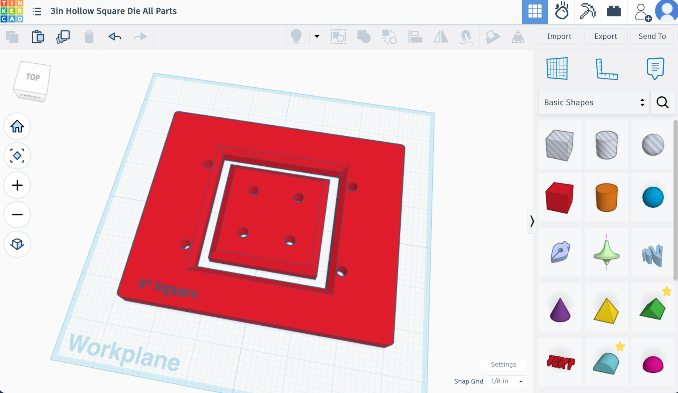
Create The Main Die Shape & Outer Hole of Hollow Shape
Shape 1 - Main die shape
Pull a red box into the workspace on tinkercad
Make it 4.9 x 5.9 inches and .4 inches tall.
Radius to .014 (mostly for aesthetics, but also avoids sharp edge which makes it easier to fit into holder)
Steps to maximum (gives more detail)
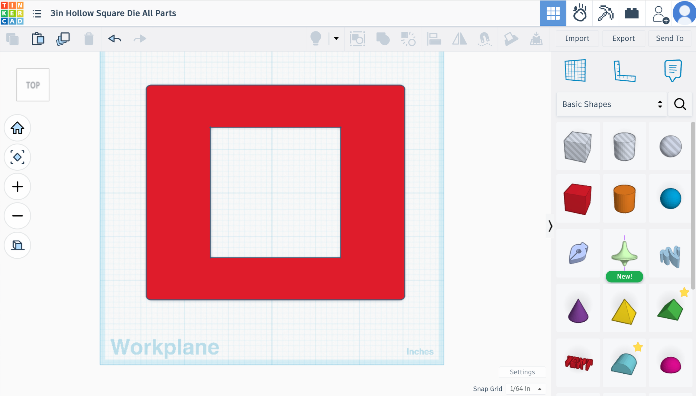
Shape 2 - Outer Hole of Hollow Shape
Pull a hole box in
Dimensions 3in x 3in x 1in
Steps to maximum
Align Shape 1 and this hole box together centered horizontally and vertically.
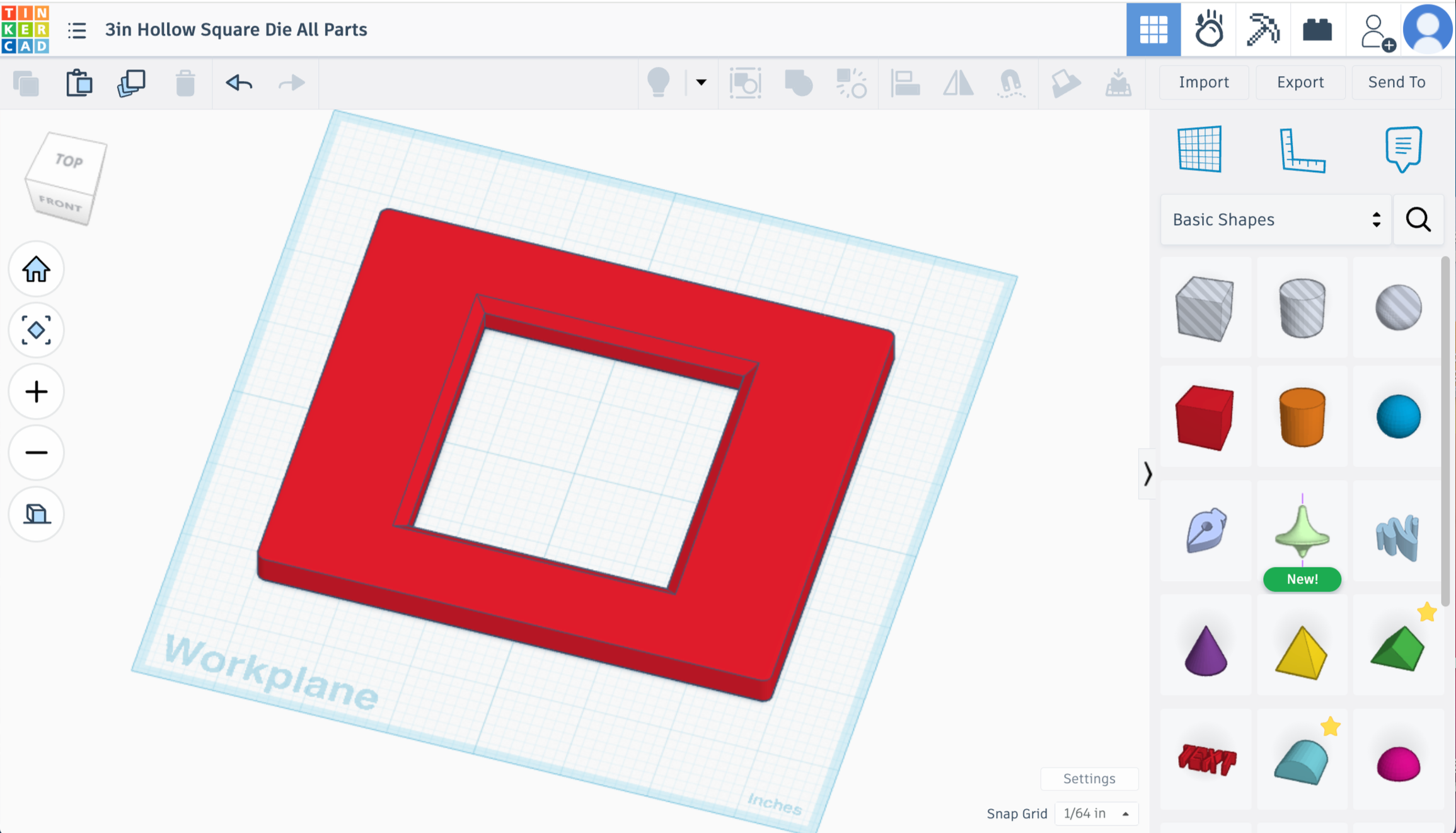
Union group
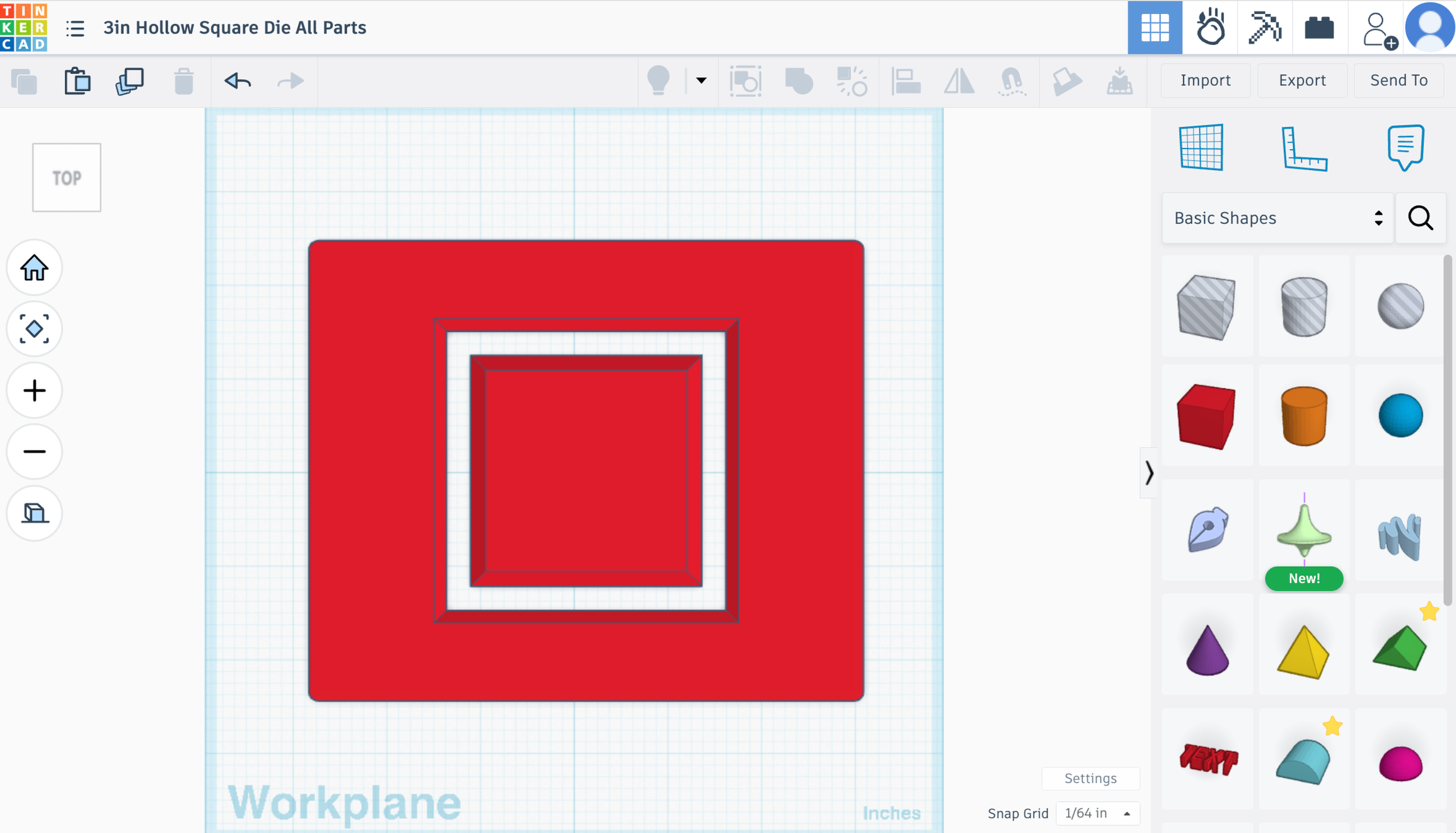
Now you have your main die shape plus the 3 inch outer hole of your hollow square.
Add a Bevel
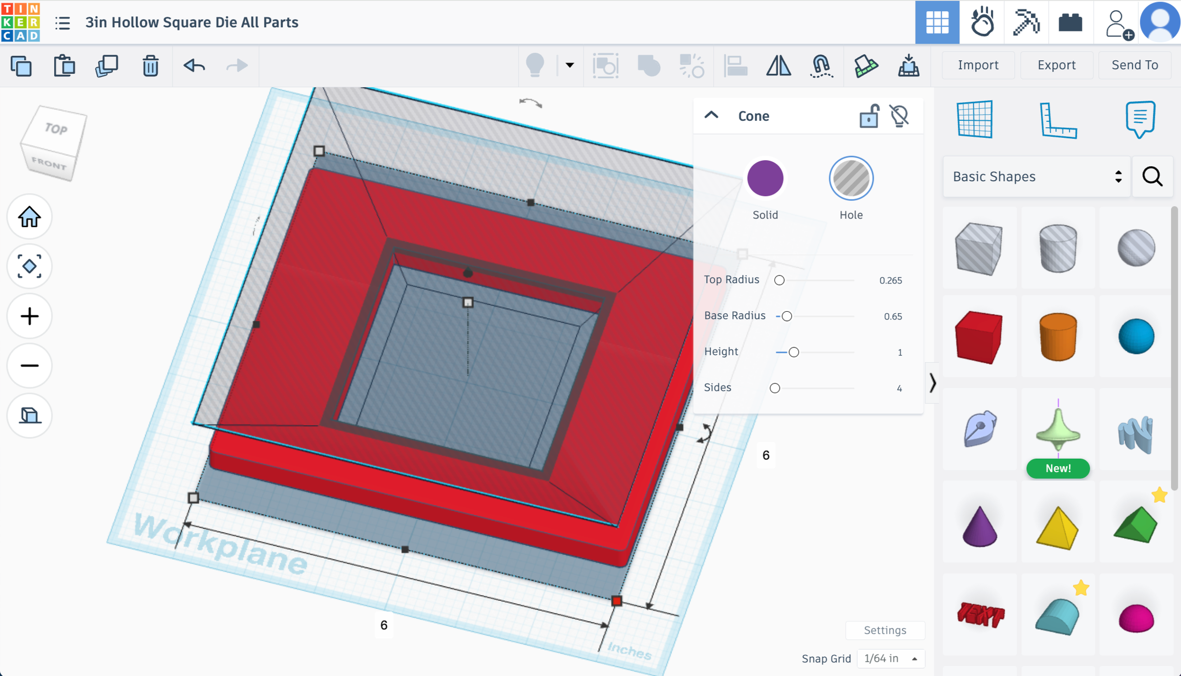
Shape 3 - Now we’re going to add a bevel
Pull in a cone
Adjust the shape settings in the pop up box to the upper right FIRST and the dimensions SECOND.
Top Radius .265
Base Radius .65
Height 1
Sides 4
Dimensions 6in x 6in x 1.75in
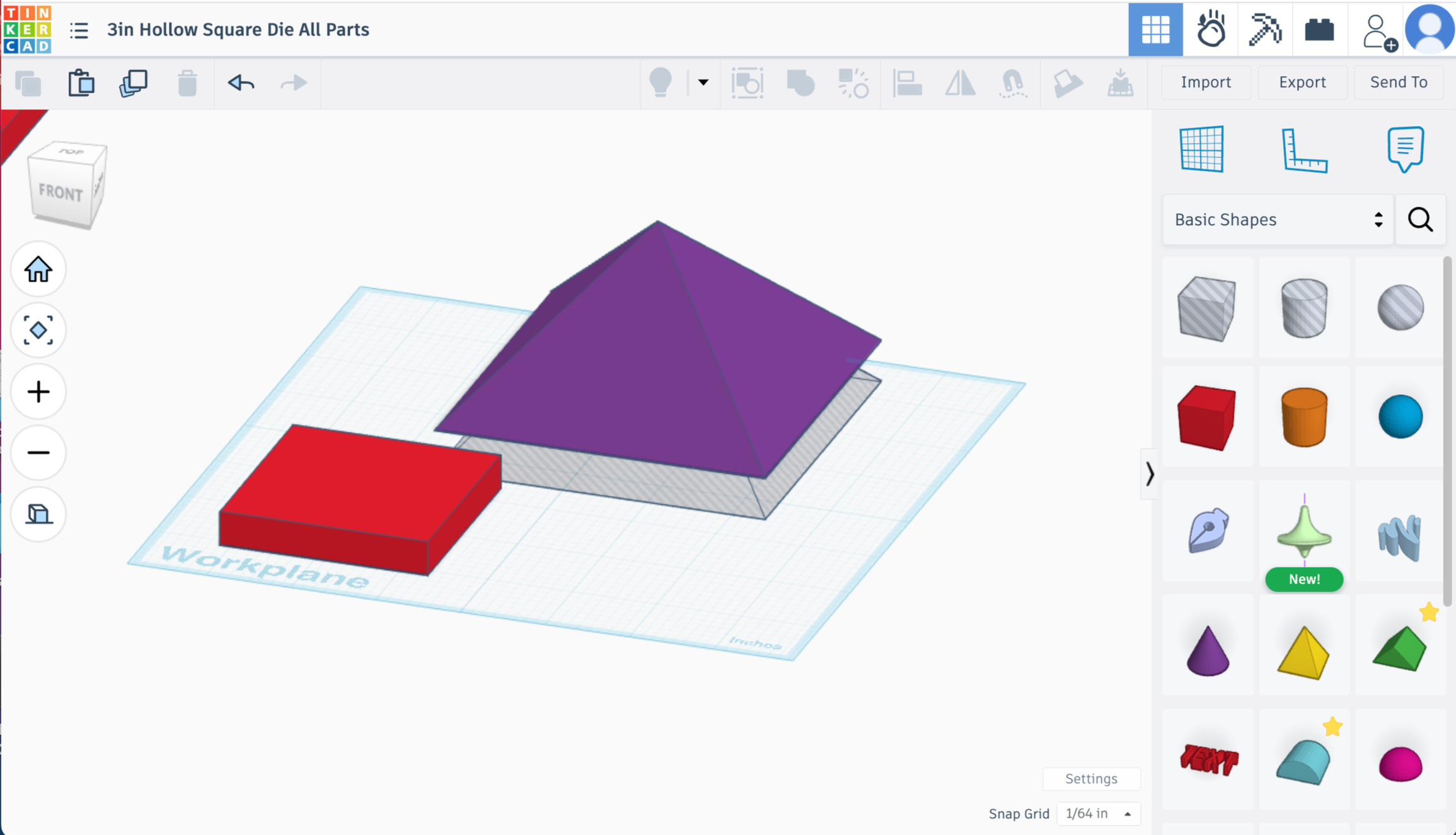
Rotate the shape 45 degrees (Left to Right) on the workplane to match the other squares
Then rotate 180 degrees (Top to Bottom) so it is upside down
Turn it from Solid to Hole
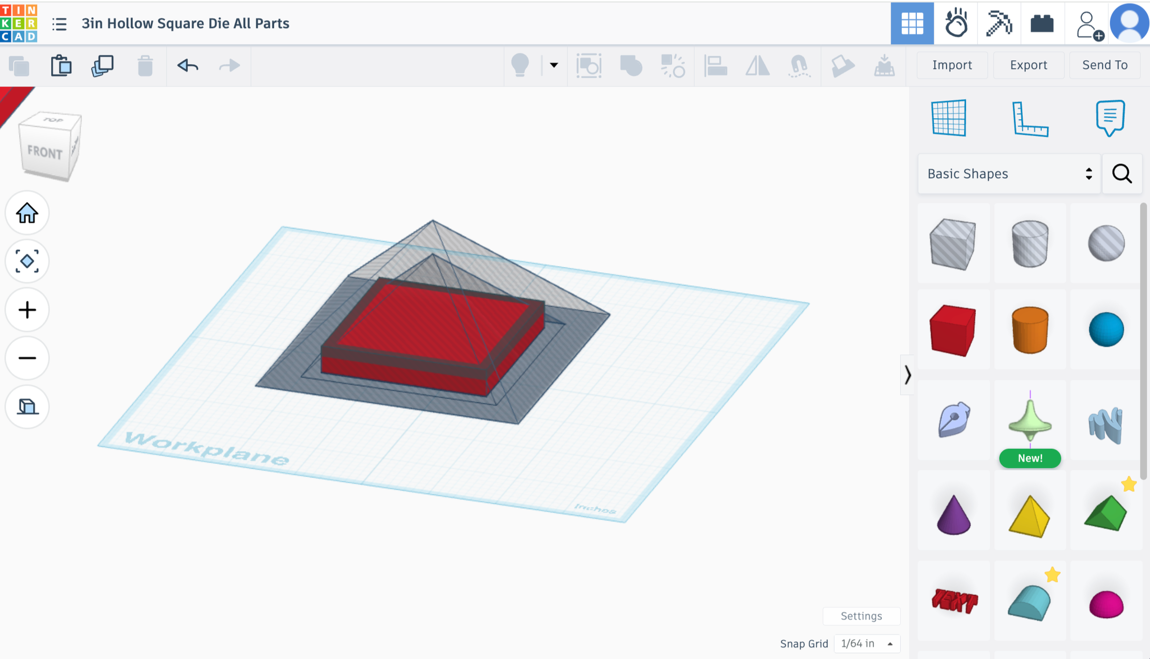
Select Shape 1 and this shape
Align centered horizontally and vertically
Union group
Create Inner Square & Bevel
Shape 4 - Inner Square
Pull a red box in
Steps to maximum
Dimensions 2.45in x 2.45in x .4in
(This will leave .275in gap all the way around from the inner square to the outer square which is just slightly larger than a quarter inch. That will be the wall thickness of your extrusion. Feel free to adjust if you want thinner or thicker walls.)
Shape 5 - Bevel
Pull in a cone
Change sides to 4 in the upper right hand pop up
Dimensions 3.9in x 3.9in x 2in
Rotate the shape 45 degrees (Left to Right) on the workplane to match the other squares
Duplicate
Push the duplicated shape down -.5in below the workplane
Turn that shape into a hole
Align the upper solid shape and lower hole shape centered horizontally and vertically
Union group the 2 shapes
Turn that new object into a hole
Select the new Shape 5 hole and previous Shape 4 square - Align centered horizontal and vertical
Union Group
Select the Inner Die and Outer Die - align centered horizontal and vertical
Completed Shape - Let’s add holes for U-Bolts!
Creating & Testing Bolt Holes
This can be tricky.
We don’t want the screws to stick out beyond the 4x4in width of the inside of the extruders upper barrel. If they’re too far out, the die won’t cleanly sit up against the bottom of your extruder. Keep in mind that the nuts holding the u-bolts in place will make them wider.
This was about the largest hollow square size I could make while keeping that border. If your extruder barrel is less than 4 inches by a little bit, you need to do some precise measuring.
Measuring the U-Bolts
Grab your u-bolts and calipers! Try to get the most accurate measurement you can from
outside of the two posts (mine are 1.46in)
inside of the 2 posts (mine are .98in)
width of the posts (mine are .24in)
We need to find the Length between the centers of each post as well. Which isn’t easy with calipers. So we’re gonna do some quick math about it.
Inside Length of two posts (.98in) PLUS Width of one post (.24in) EQUALS (1.22in)
This is the length between the center of each post. We can use this measurement regardless of the added tolerance on the cylinder to make sure they are spaced correctly.
You can go by the measurements given to you by the manufacturer, but I found those to be not quite accurate for the brand I bought. Maybe you’ll get lucky!
NEED PIC of ubolt with dimensions
We’re going to place 2 cylinders on the workplane in the exact distance away from each other that they need to be. Then we’ll save that as a custom shape creation so it can be used again the future. Once this custom spaced out shape is created we can print a test piece before printing the entire die to make sure the fit of the ubolt holes is correct.
Creating the Custom Hole Shape on Tinkercad
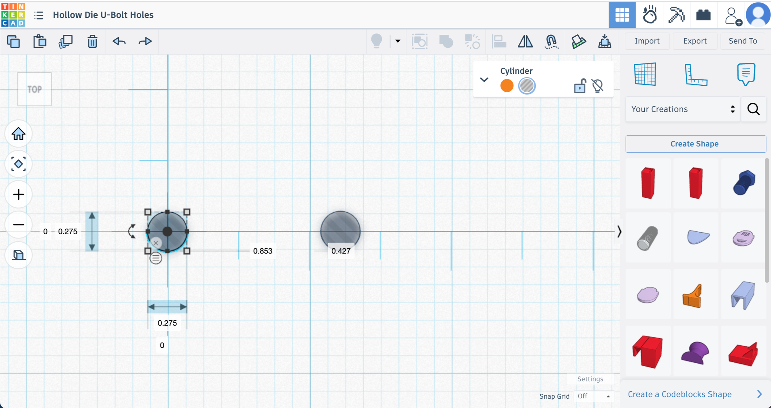
Create a new TinkerCad file
Drag a hole cylinder onto the workplane
Sides and segments to max
Make the cylinder the same diameter as the posts on your bolt plus some extra for extra tolerance.
(Mine were .24in, so I made the cylinders .275in.)
Pull in a Ruler (make sure Use Midpoint is on)
Align your cylinder to the midpoint
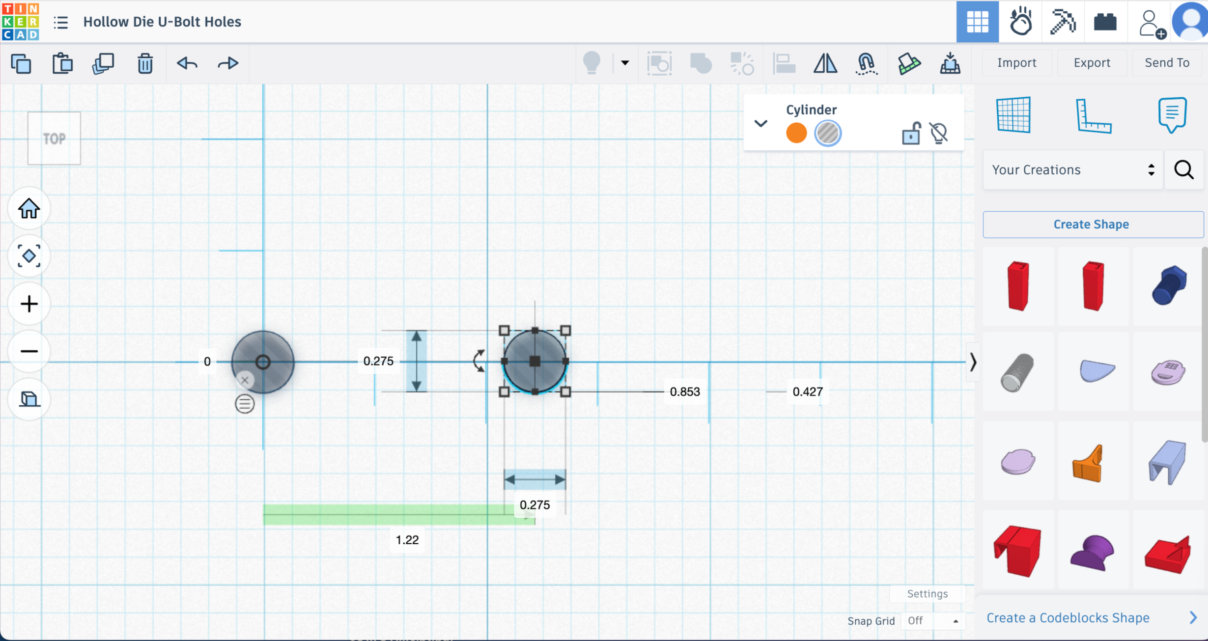
Copy and Paste another cylinder
Pull that cylinder out to your center point length (Mine is 1.22in)
Union group
Save as a custom shape by clicking on the basic shapes dropdown, choose “your creations” and then click custom shape.
Add name “Bolt Holes V1”, put the dimensions and spacing info in the description, choose “hole” in settings, choose “prevent editing” and click the box for “lock part size”
Now do this a second time with slightly wider post holes to test out a second spacing option. You could even do 3 or 4 tests if you want. Save each one as V1, V2, V3, etc.
Creating Your Test Square
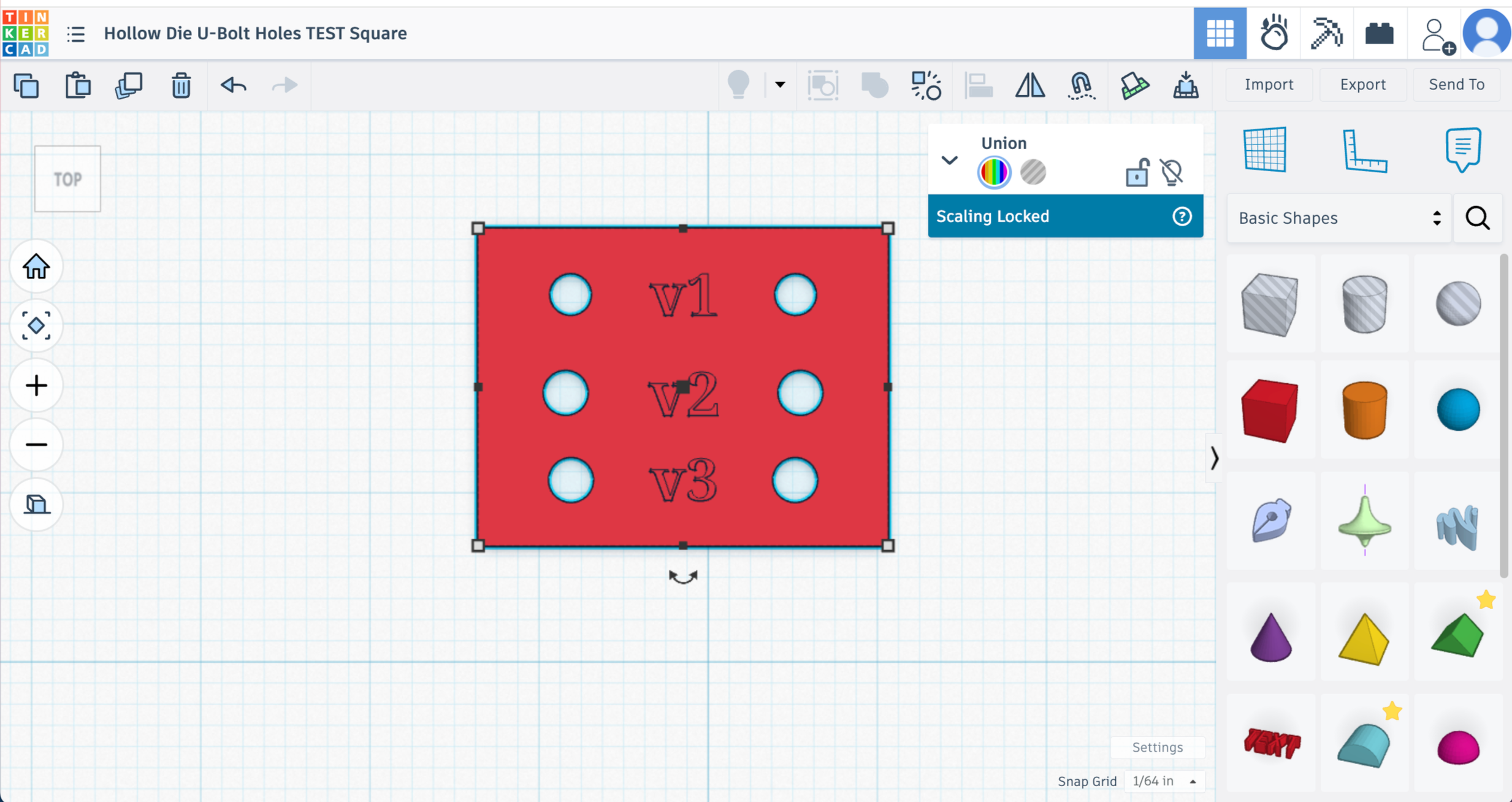
Pull in a box and make the dimensions big enough for your tests and .4in height
Align the Bolt Hole tests on the box
Use the text feature on TinkerCad to put a V1, V2, or whatever your identifier is next to each test.
Union group
3d Print your hole spacing test and test your U-Bolts! If one of the tests works well without too much force needed - that’s your guy! If none work, adjust as needed and retest.
You don’t want much resistance or having to force the bolt into the holes. It’ll be much worse when you have 4 bolts that you need to get in.
Make sure you’re writing down all the dimensions and measurements somewhere safe!
Adding the Bolt Holes to the Die - We’re almost done!
Now that we know the spacing and sizing of the bolt holes - we can add them to the die.
Open your file for the 3in Hollow Square Die
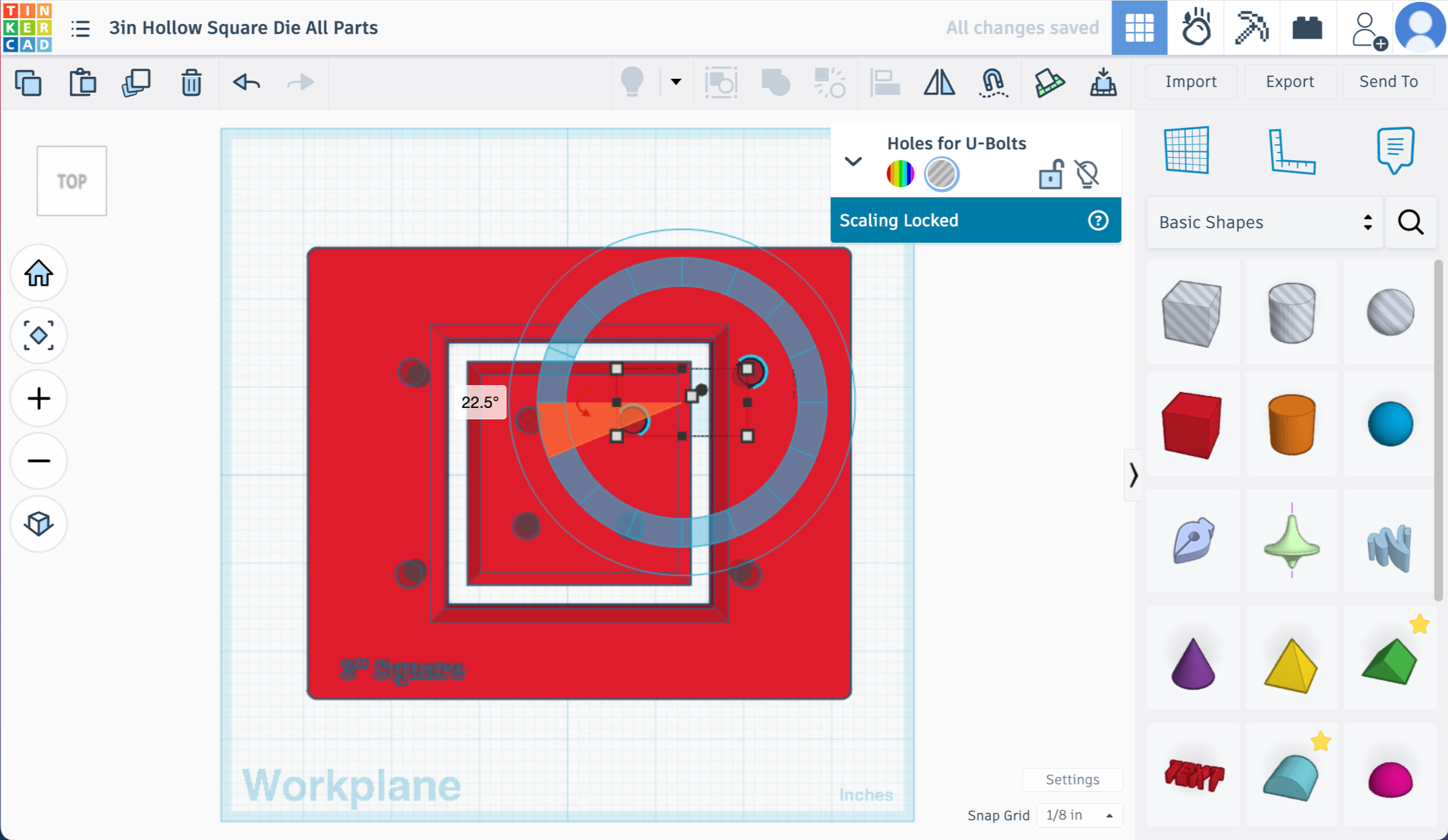
Go to your custom creations and pull in which ever Bolt Hole version worked the best for you
Rotate the custom shape by 22.5 degrees
Position it so that one hole is on the inner die square and one is on the outer die
Duplicate and rotate as needed to position on set of holes in each corner of the die.
Tip - You can pull in a box and set the dimensions to match your barrel size, center align it with the main outer die shape to make sure you’re keeping everything inside of that square. Make sure to account for the extra space the nuts will extend from the bolt.
Use the text function to put a description of the die on there if you’d like. I usually push that text down into the die about 1/8 of an inch or so.
Once you’re happy with the placement of all 4 sets of holes. Union group everything and you have a finished die!
Wow - we did it!
Please reach out if you have questions, comments, or to you used this tutorial. I love to hear from people! Email or instagram are the easiest ways to get a hold of me.
Happy extruding!